Printable Bases
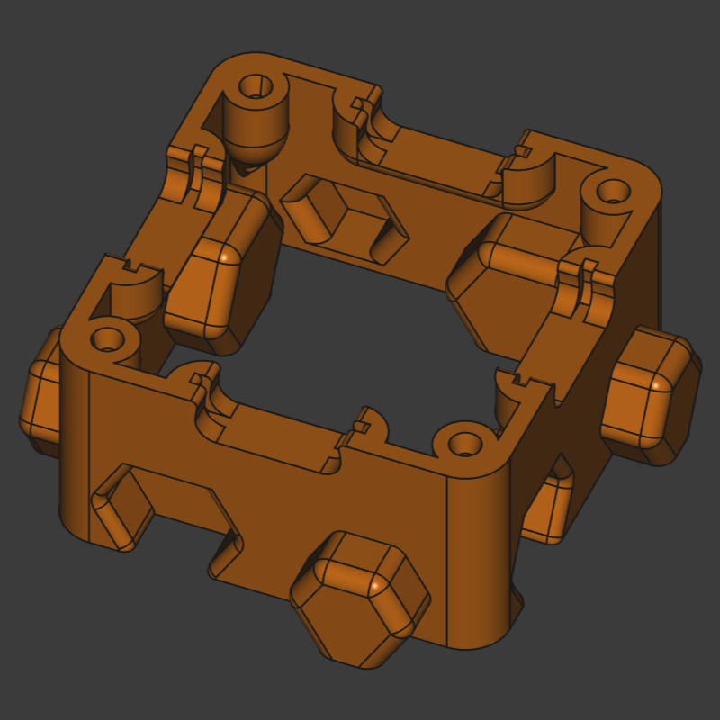
The printable base provides mounting for all parts and helps aligning the puzzle pieces. The printable base weights approx. 10 grams and carries a few design details that support assembly.
Files & Tools
- All base models are in FreeCAD format (
.FCStd) in theprintable-basesfolder of the repository. - All common parts already exported as STL and STEP for immediate printing
- The Open design is for easier repairability without disassembly and better stackability
- The Magnetic variant is for enclosing sensitive components in the inside of the part and for optional magnet holder (blackboard use)
Print Parameters
The printable base is highly optimized for perimeter printing, i.e. the slicer will generate 90%+ perimeters and 10%- infill etc., thus, many settings are unimportant. Use these general settings:
- Layer height: 0.20 mm
- Wall (perimeter): 2 shells
- top and bottom layers: 10
- Infill: 100 % (for filling the few small non-perimeter-wall sections)
- Support: not required
Preparation before Batch Printing: Tolerances & Test Print
FIRST PRINT a tolerance tester piece (folder tolerance-tester/)
containing one screw hole and one magnet connector tester. These parts summarize all tolerance/clearance classes so you can verify your printer capabilities. There is nothing worse, than batch printing bases and figuring out they do not met the criterion for good assembly and alignment. The test parts are quickly printed.
Screw Hole Tolerance
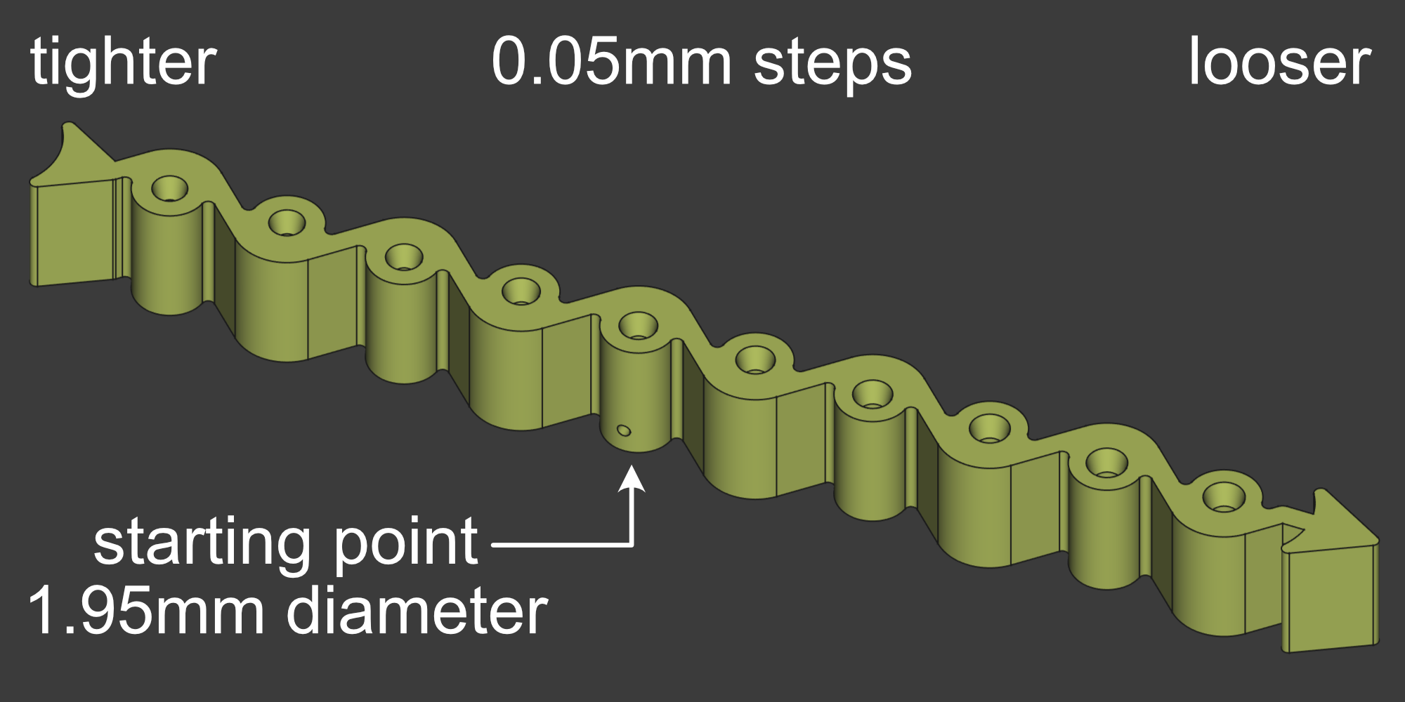
The screw hole tester is an oriented part that habors ten holes with increasing diameter in 0.05mm increments. A side hole marks the imperically found best hole size for the average printer and the typical needed bore size of self-tapping M2 screws, 1.95mm. The available STL and STEP models are designed with 1.95mm holes in mind, which gives self-tapping screws the right amount of freedom to form threads into the plastic and the deformed plastic filling the gaps between the threads. However, you might find that choosing a hole size slightly larger or bigger to suit your printer model and filament choice better.
Screw in M2 screws in every hole and determine which screw size feels best. When to tight, the screw strips or the screwdriver cams out and rounds the screw head. When too loose, the screw strips the plastic when over tightening the PCB down to the printable base.
If you find yourself, for instance, that 1.95mm is too tight for the screw and 2.05mm feels significantly better, then you can use the hole compensation feature of your slicer to enlarge the 1.95mm hole to 2.05mm, i.e. hole compensation +0.1mm.
Connector Pocket Tolerance
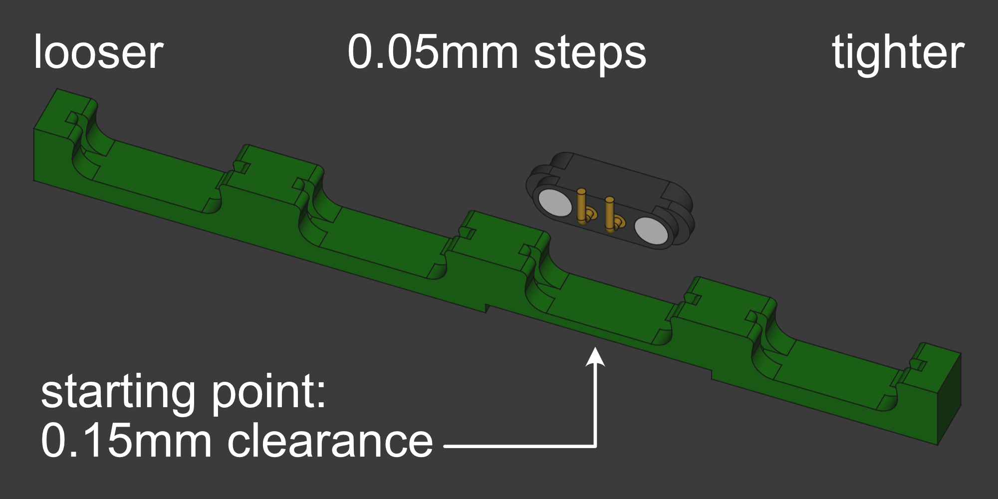
Four tolerance classes are provided per default for the magnetic connector pocket:
| Dimension | Clearance |
|---|---|
| 0.10 mm | tight fit, for very precise printers or when minor underextruding happens |
| 0.15 mm | normal fit, start here |
| 0.20 mm | looser fit, easier insertion |
| 0.25 mm | loose fit, when printer overextrudes when printhead is cornering |
Ideally, the magnetic connector fits in 0.15mm clearance pocket by gently pressing it in with your fingers, so the magnetic connector cannot wiggle in its pocket. If you need a plier to press it in, then it is too tight. If none of those clearances work for you, you should first look into calibrating your printer.
Base Alignment Nose Tolerance
The hexagonal protrusion and indentation helps aligning the bases, so the magnetic connectors connect flush. Therefore, the tolerance should be chosen small enough for excellent alignment and wide enough so the parts can slide virtually frictionless. A tolerance of 0.2mm is is typically sufficient (making it slightly less than 0.4mm clearance in total) and is in reach of all recent printers.
Batch printing
A standard size printer can carry 20 - 25 bases on one print plate. One base is printed in less than an hour, thus, one print plate is printed in less than a day.
You can either batch print the bases in an over-night print job or head over to Sourcing & Manufacturing, where you can find hubs that help you sourcing printable bases.
That’s all you need for the “printable bases” step. Next, move on to Assembly Instructions where the PCBs, magnets and screws are brought together.