Assembly Instructions
Overview
This guide walks you through assembling Circuit Nodes from individual components. Whether you’re building from scratch or preparing a pre-made kit, these steps apply.
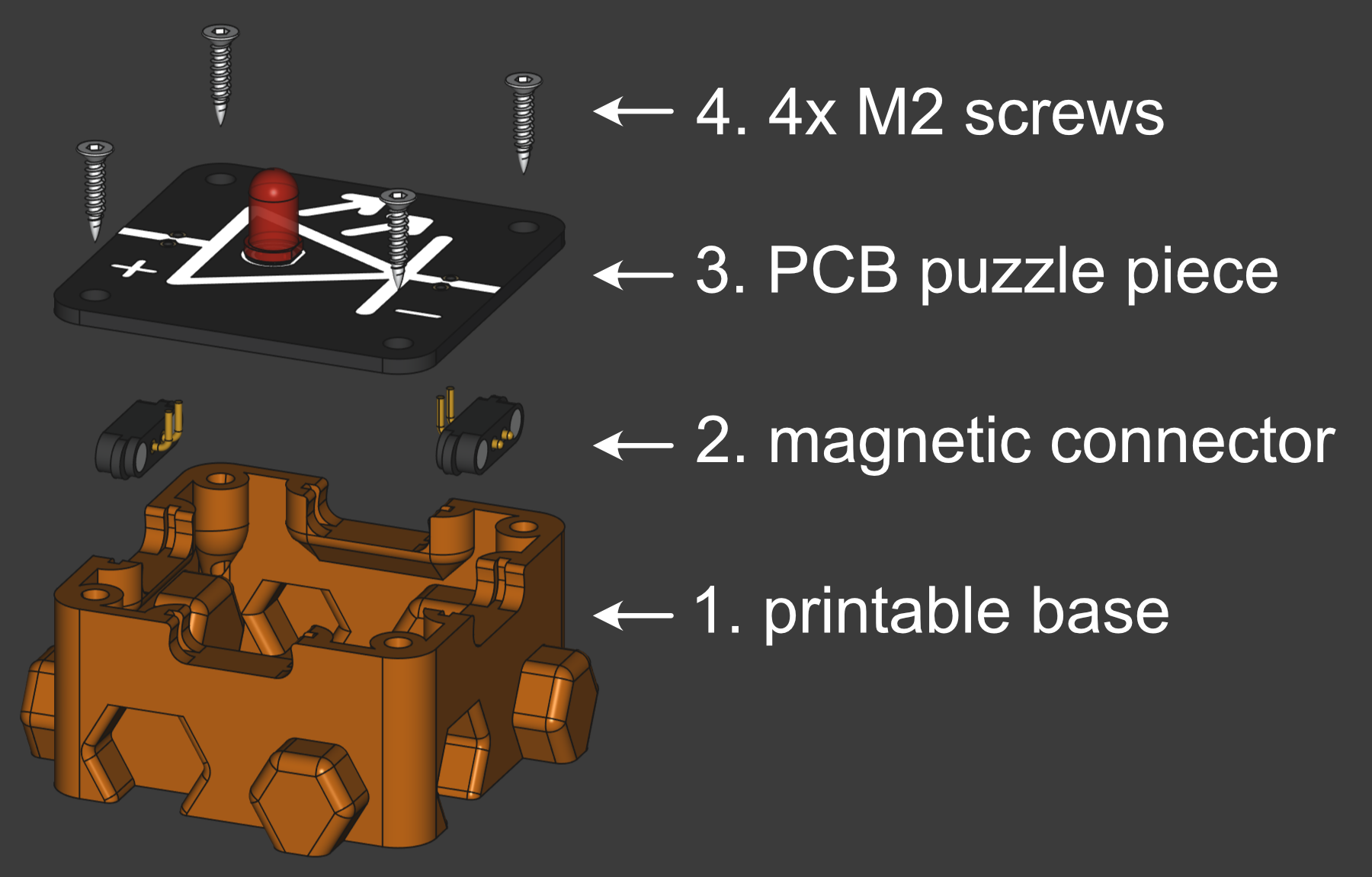
Below are the three parts that come together: the printed base, a magnetic connector, and a populated PCB.
Pre‑Assembly
Prepare your PCB by soldering the required components. Double‑check the silkscreen for correct orientation and values. Trim leads and clean flux residue. A quick continuity check with a multimeter catches shorts before the board is placed in its base.
You will need:
- populated PCB
- printed base (match the tolerance test)
- 4× M2 self-tapping screws (optionally heat inserts)
- magnetic pogo connector
- soldering iron, solder, and basic hand tools
- multimeter for verification
1. Base Preparation
Take a few printable bases and check if the can be plugged into each other without too much friction. Remove print defects such as floating filament pieces from bridging that can interfer with the fitting of the parts.
2. Magnetic Pogo Connector
Insert the corresponding number of magnetic pogo connectors for the circuit node, e.g. two connectors on opposite sides for an LED, two adjacent connectors for an 90° angle, etc. Removing a wrongly inserted magnetic connector can be difficult due to the tight clearances, be careful.
Sourcing: Magnetic pogo connectors from LCSC, AliExpress, Taobao, or directly from the manufacturer Samzo Components. Look for 2-pin spring-loaded pogo connectors with integrated magnets and small wings for alignment and 2.54 pogo pin spacing. Note: this part can experience stock delays; plan ahead.
3. PCB Preparation
Solder components to PCB. PCB silkscreen indicates values and parts needed. Magnetic pogo connector can be soldered as a last step after assembly, so you do not have to worry about double-sided soldering. Check if the PCB benefits from reflow soldering.
4. Screws and Connector soldering
Hold the board in place and insert the four screws loosely. Once all screws are started, tighten them in a cross pattern until the board is seated; do not over‑torque. The PCB should lie flat and not shift when nudged. Lastly, solder the connector to the board (if not already done).
That’s it – the module is assembled.