Introduction
![]()
Teaching electric curcuits is a challenging task. Of the various physics subjects, this is the first physics subject which cannot easily be experience with our senses in a satisfying way and teachers heavy rely on proxies for electricity, e.g. a lamp that “magically” is light up.
For an enjoyable learning environment, hands-on experiments and experience are vital, however, electric circuits are not without danger, thus, properly designed teaching material is required.
Why Circuit Nodes?
Consider the typically schematic or circuit diagram. All typical electronic components have a dedicated symbol that represents them in a diagram, see below. One can quickly grasp the intent of the diagram.
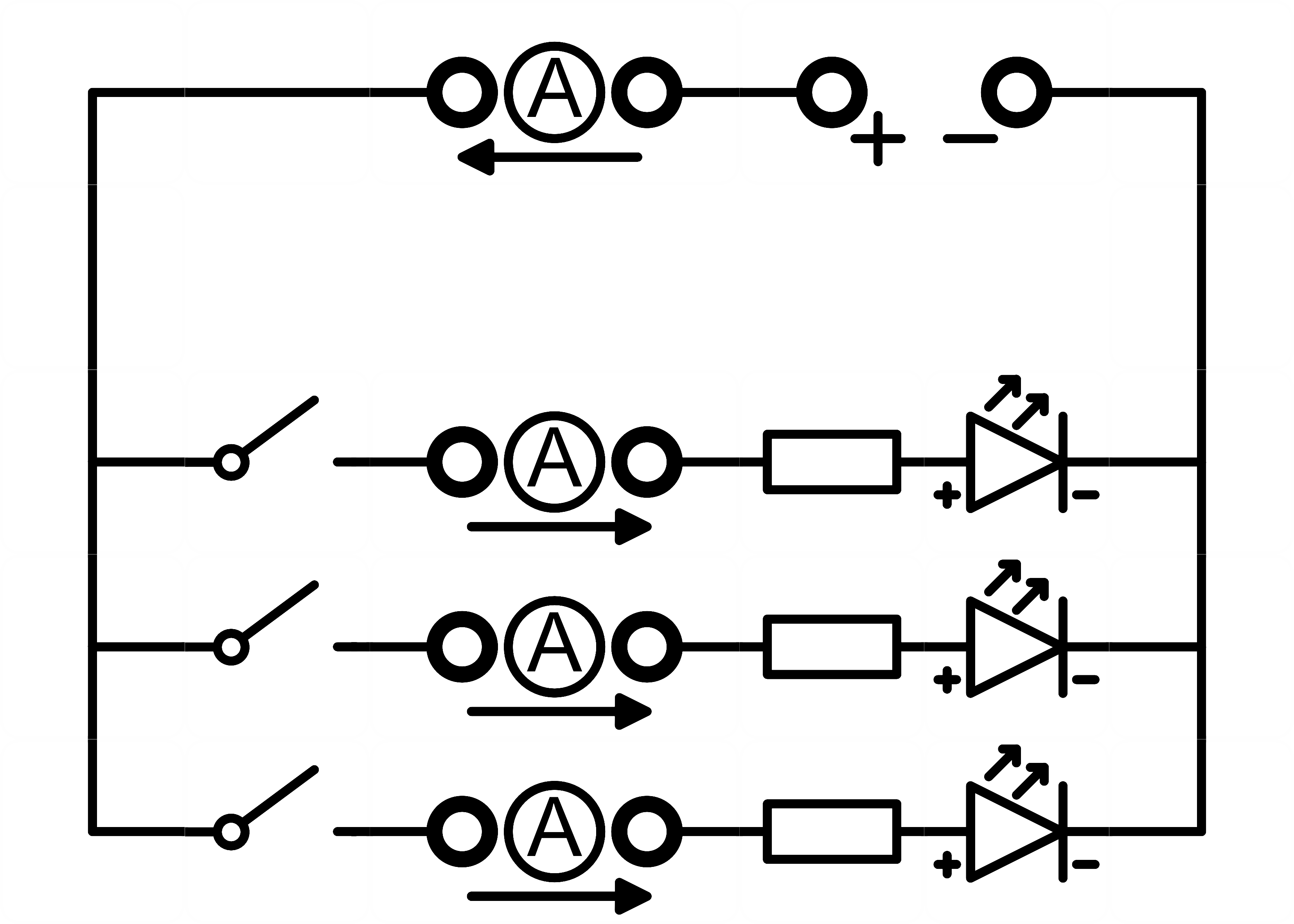
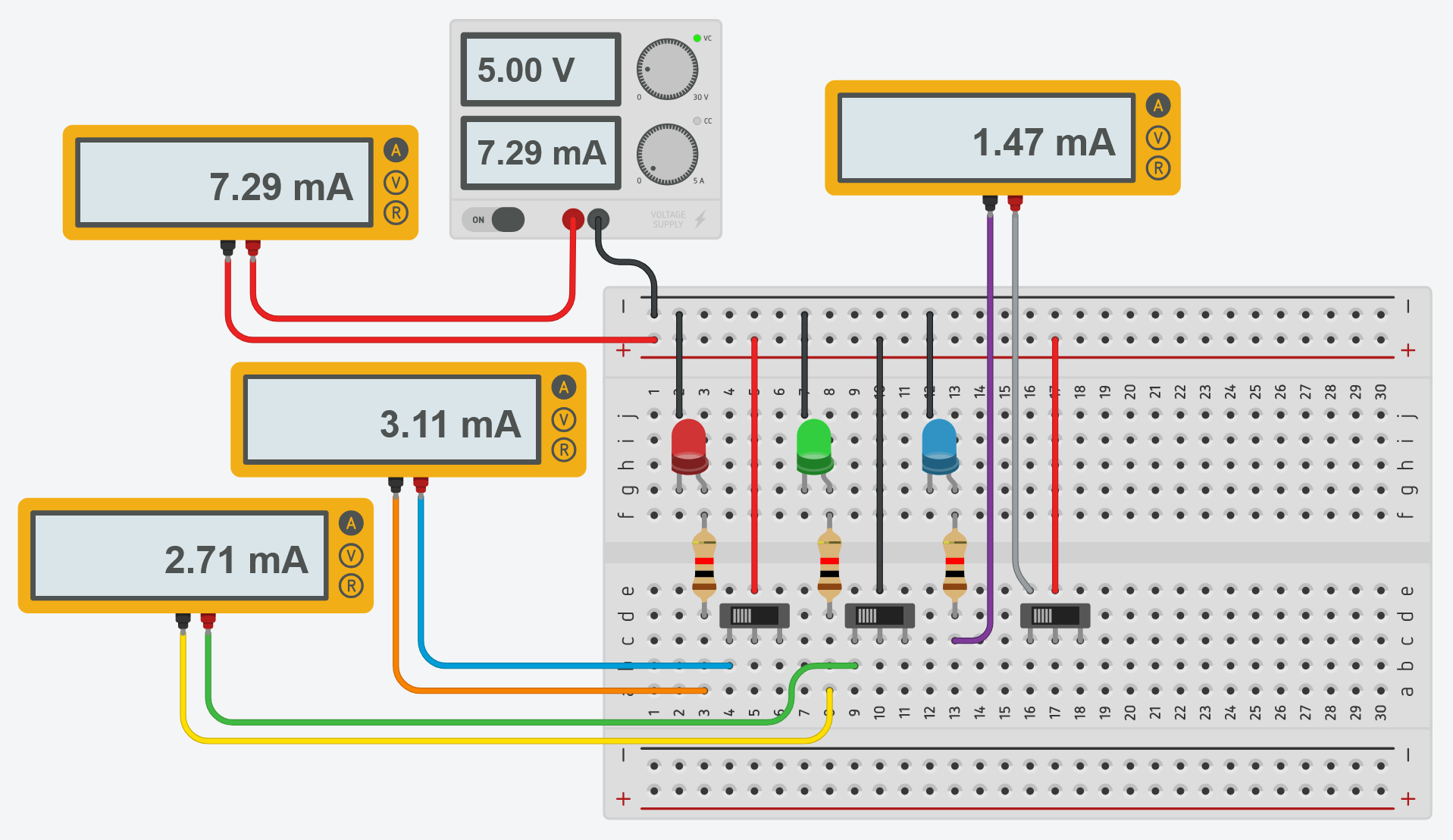
Unfortunately, this is typically not the way how such an electric circuit is build in real life. A student might build a well-structured circuit on a breadboard, see below, but experience tells that this is rarely the case. First-hand experience with electronic circuits on breadboard level is oftentimes… less structured (if sucessful at all…).
Circuit Nodes is an open‑source, 3D‑printed modular system for teaching electric circuits in schools.
Secondary‑school students learn best when the tools they use resemble the textbook diagrams they are taught. Conventional kits (breadboards, loose wires) force pupils to translate between two very different representations; this translation is a major source of persistent misconceptions about current, voltage and circuit behaviour.
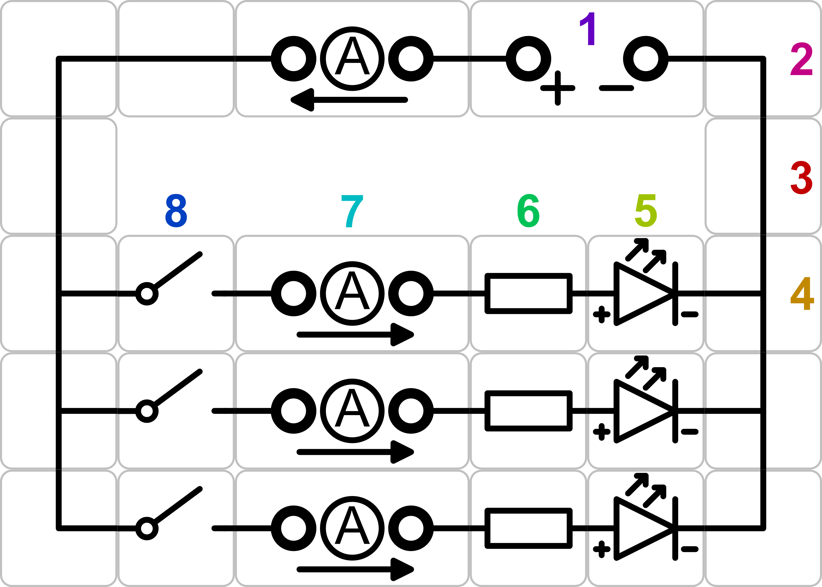
The upper circuit can be segmented in functional parts on a grid, providing a puzzle-like system with repeating elements, the origin of the Circuit Nodes. Only eigth unique elements construct the upper circuit, where every single element is simple to grasp.
Circuit Nodes remove the translation and representation barrier. Each puzzle piece is its schematic symbol, and modules snap together on a square grid. Magnets and geometry make incorrect wiring virtually impossible, so students (and teachers alike) can concentrate on the physics.
The system can be summarised as inexpensive, easy to adapt to lesson plans and effective at reducing abstraction.
The idea and evaluation is further outline in a peer‑reviewed paper: “Modular 3D‑printed Circuit Nodes for low‑cost and hands‑on Electricity Education” (Phys. Educ. 61 015010, 2024, DOI 10.1088/1361-6552/ae1abd).
Practical Examples
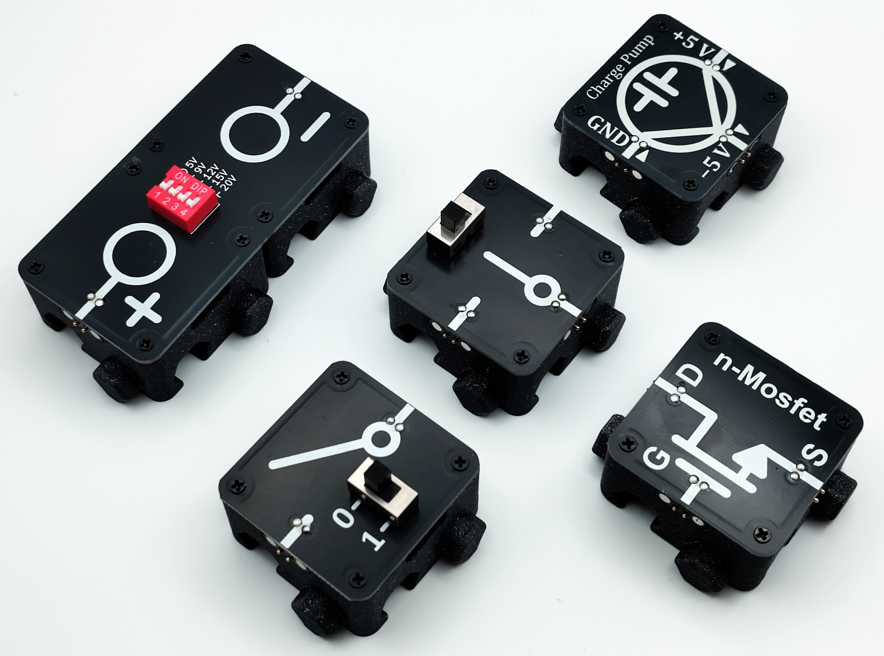
Here are some examples of Circuit Nodes, ranging from basic banana terminals for voltage and current supply and measurement,
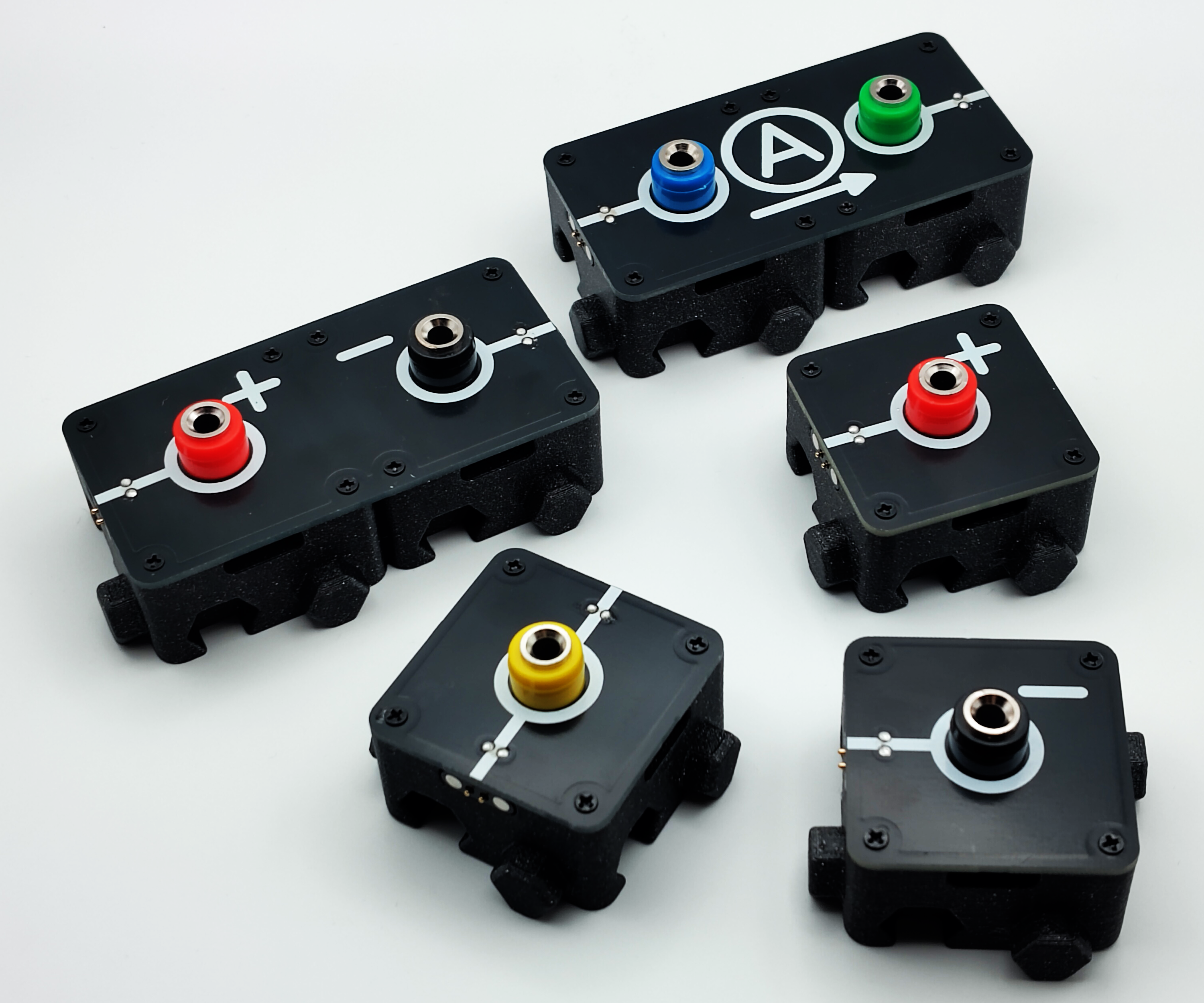
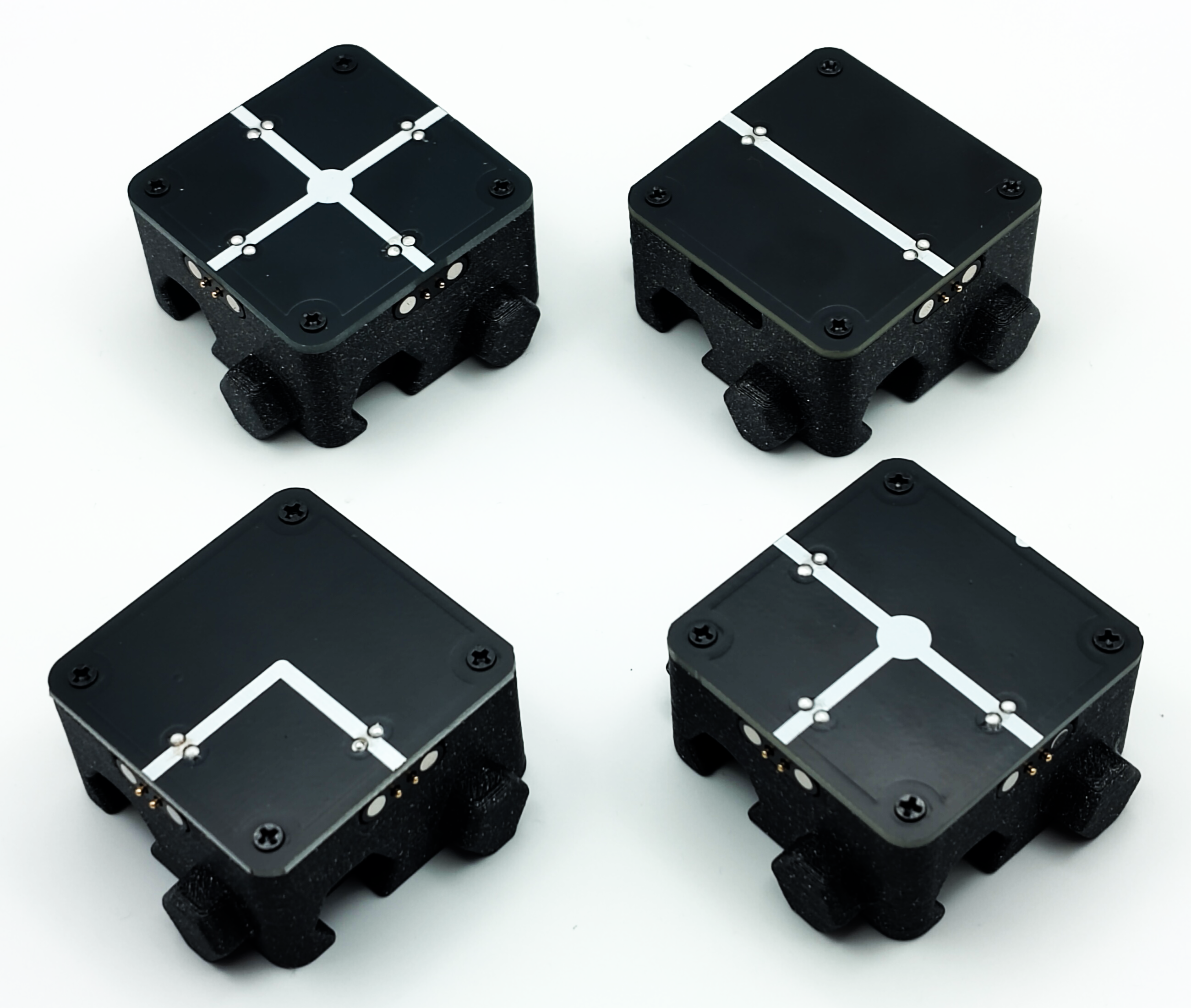
over to wire segments and junctions,
ending with functional elements, like switches, lamps, LEDs, capacitors, and advanced components,
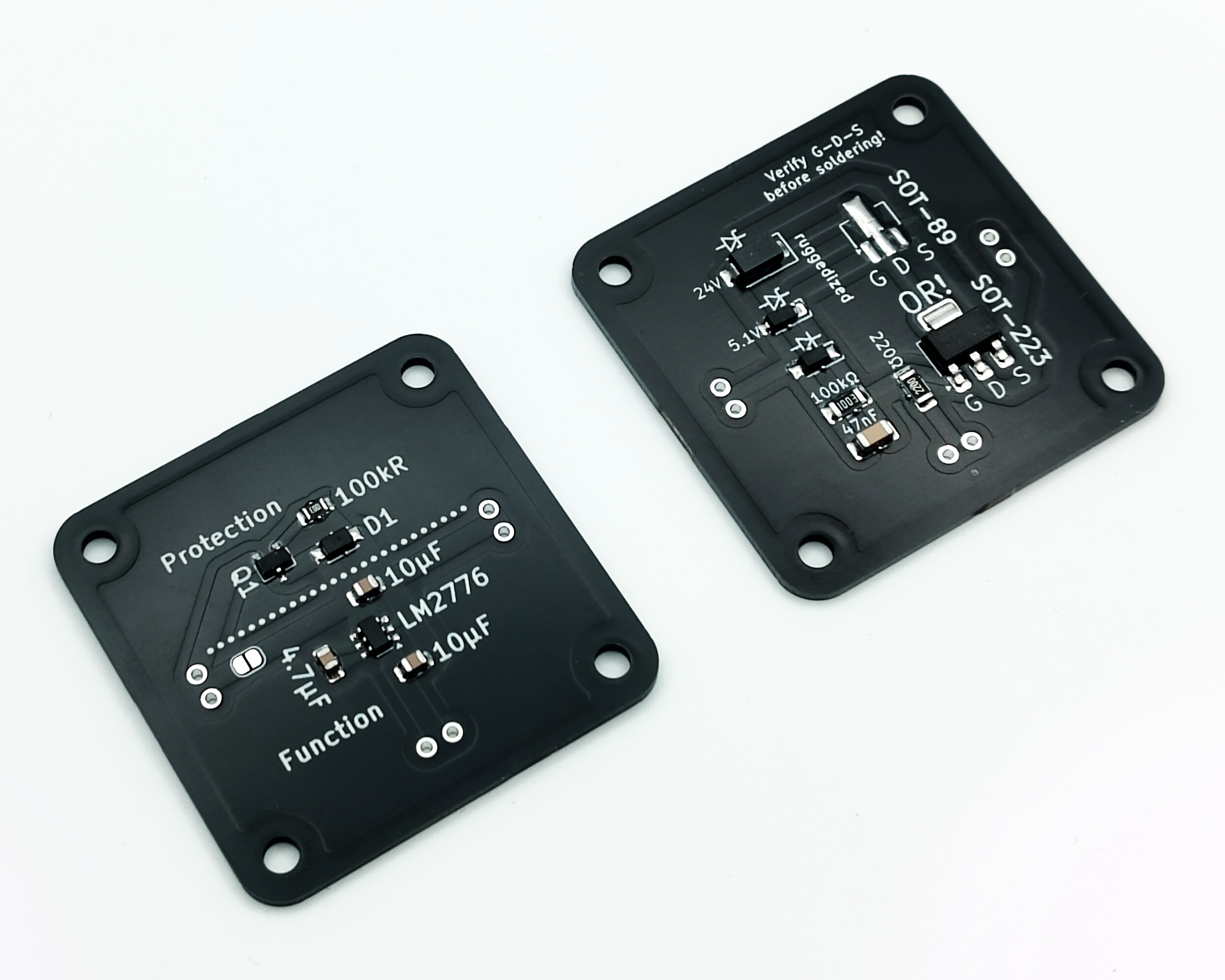
Worth noting, many sensitive and advanced components also come as “ruggedized” versions, where additional protective circuit elements are added, hidden on the underside of the board, enabling students to explore those components without the risk of causing damage to them (and subsequently time investment to repair those again).
What’s in this repository?
All files and informations are provided in this repository for building your own Circuit Nodes:
- Schematics and Gerber files for every PCB module.
- FreeCAD models plus STL/STEP exports for the 3‑D printed bases.
- Assembly instructions, example circuits and documentation.
- A bill‑of‑materials and production notes for magnets, screws, and components
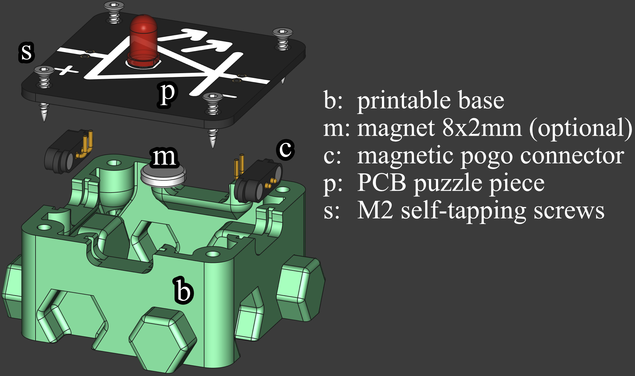
- Source images such as
assembly.pngused throughout the docs.
Ready to get started? → Getting Started Guide