Getting Started
The Basic Concept
Circuit Nodes are modular PCBs that snap together on a square grid to form real circuits. This page gives a quick overview before you move on. Each puzzle piece is a PCB with a single component; the edges carry magnets that provide both the mechanical and electrical connection. Modules are arranged on a grid and the schematic symbol is printed on the board so the layout matches the diagram.
Research shows that translating between flat schematics and messy physical builds is a major obstacle in school circuits. Circuit Nodes remove that step: the arrangement pupils draw is the arrangement they build, so they can concentrate on the physics.
Components
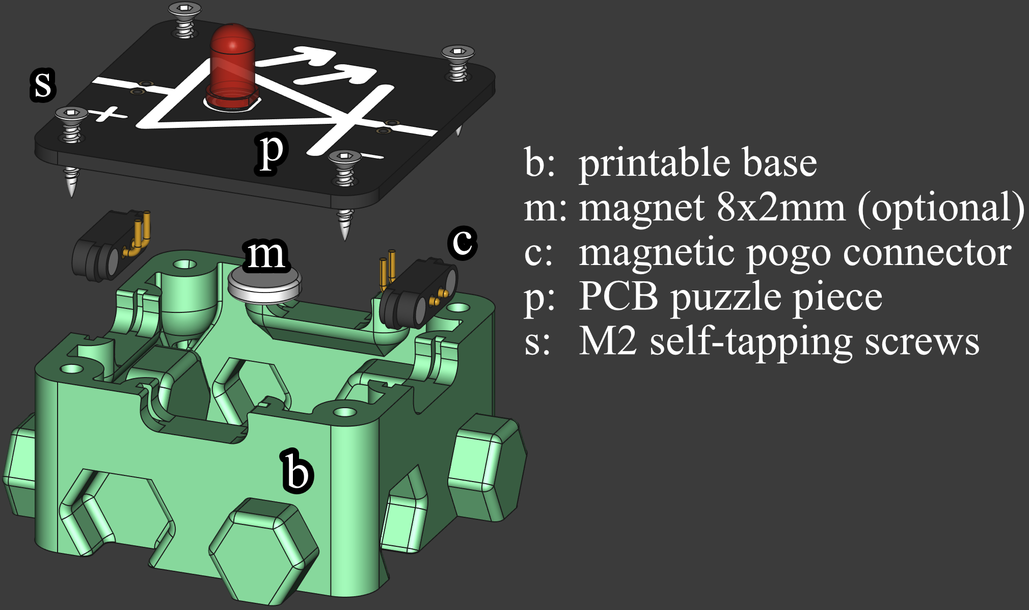
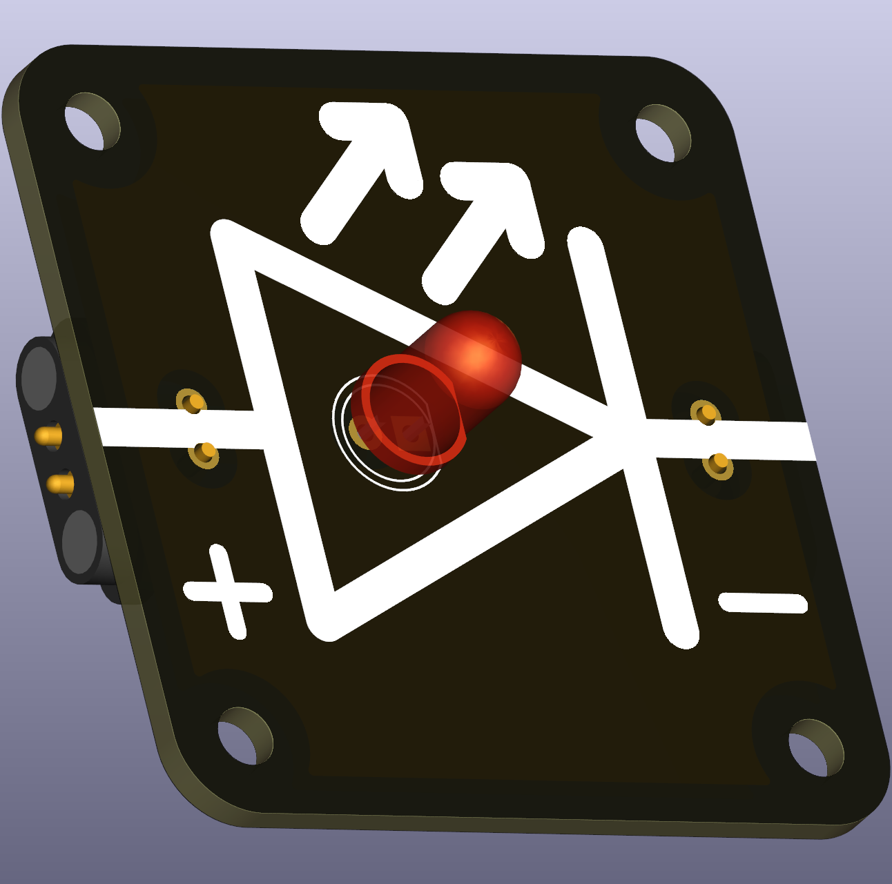
1. Puzzle Pieces (PCBs)
Small circuit boards with:
- Active components (resistors, LEDs, switches, etc.)
- Passive components (wire traces, connections)
- Schematic diagram printed on the silkscreen
- manufacturing files conveniendly provided here
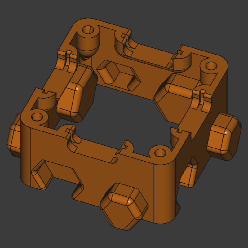
2. 3D-Printed Bases
Frame that holds the PCB with:
- Interlocking puzzle-like edges
- Pockets for magnetic connectors
- M2 screw mounting points
- Various style options (open-bottom, magnetic-bottom)
- also provided here as STL, STEP and FreeCAD source file
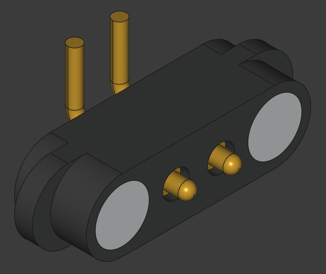
3. Magnetic Connectors
Small magnetig connectors found in detachable charging cables that:
- Provide physical attachment between pieces
- Act as electrical contacts for circuit connections
- Enable quick assembly and disassembly
4. Further Components
Additional modules introduce core circuit elements:
- Lamps for visible load behavior and current draw
- LEDs for polarity-aware visual feedback
- Resistors to set current and divide voltage
- Magnets for optional magnetic base, ideal for blackboard use
Together, these parts let you build a wide range of beginner and intermediate analog circuit examples.
Getting Your First Kit
Circuit Nodes are Open Source and all manufacturing files are included in this repository. Since there are many different puzzle pieces available and some are needed multiple times, e.g. wires and measuring nodes, starting with a curated kit is recommended.
The DIY path is:
- Download Gerber files from the repository
- Order PCBs from a fabrication service
- Source magnetic connectors and screws
- Print the bases on a 3D printer
- Assemble following the detailed instructions
If DIY is not an option, then a manufacturing and assembly service is provided, see below.
Curated, Pre‑Made Kits
Ready‑made sets are offered at different levels, approximately aiming for different educational levels/classes.
this section is under construction
- Entry‑level kit – power, basic modules for lamps and switches
- Intermediate kit – adds measurement nodes, resistors and LEDs
- Advanced kit – full classroom curriculum set
Build Your Own, Expand your Collection
When you already have a set of circuit nodes with wires, junctions, banana terminals and switches, then you can easily expand your kit by adding components your are interested in.
Head over to the puzzle piece folder of the repository and search the list for the the components your are interested in. If you cannot find a certain component, then create a issue/discussion and the component will be designed for you.
Ask for Manufacturing and Assembly Service
Ordering PCB and assemblying Circuit Nodes might be too overwhelming and time-consuming for some. We offer Manufacturing and Assembly Services at Leipzig University at cost neutral level. Reach out to us.
What You’ll Need for Assembly
To start using Circuit Nodes:
Minimum Setup
- PCBs - At least 3-5 basic pieces to form a simple circuit
- 3D-Printed Bases - One per PCB
- Magnetic Connectors - About 2 per piece (depending on connections needed)
- M2 Screws - 4 per base (self-tapping or with heat inserts)
- banana terminals - for measuring voltage and current at given nodes
- Power Source - USB-C PD or benchtop supply depending on circuit and PCBs
Next Steps
- To build circuits: Continue to Assembly Instructions
- To explore components: Check out Component Guide
- To understand base options: See Printable Bases
- To learn manufacturing: Read Sourcing & Manufacturing
Have questions? Open an issue or discussion on GitHub.